Marrying 200 years of Technology
Set deep in the Wiltshire countryside, our historic Boulton and Watt and Harvey beam engines are still working today, able to keep the Kennet & Avon canal full of water just as they have done since 1809. They work at full load pumping over 10 cubic metres a minute, making them the oldest working examples in the world.
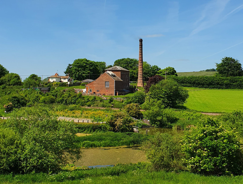
We have a duty of care to ensure our engines continue to run safely for future generations. Our key aims are to understand and prevent any damage to the engines and to see if we can make any changes to reduce stresses. To do this, with the help of Bath University students and graduates from the Atomic Weapons Establishment (AWE), we have invested in some 21st century technology to monitor their vital characteristics.
Known as Mechatronics, we are able to replicate mechanical methods devised by James Watt, and used for many years to understand the performance of steam engines. We are using a Dewesoft system, extensively used in F1 racing cars and aerospace applications.
So far we have installed a number of sensors to monitor and record pressures, temperatures, movement of the engine and the timing of valves. Armed with this data, which is freely available to accredited academic establishments, we can look for early signs of where maintenance might be required and immediately understand any changes in performance.

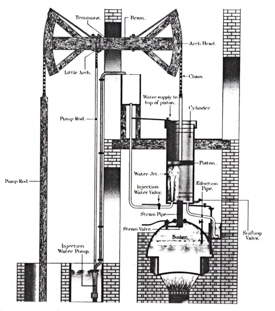
Measuring the performance of such engines is not a new idea. Since the early days of steam power there has been a need to maximise the work done against the amount of coal consumed. In the early days this was described as the ‘Duty’ of a pumping engine measuring how many pounds of water could be lifted (lb x ft) per bushel (around 90 lbs) of coal. For very early engines the Duty number was around 10 million. Over the years James Watt, Richard Trevithick and others improved the performance of engines raising the Duty to over 40 million. We think the number for our engines is around 20 million which is not bad for a 200 years old machine.
Another important measurement, also devised by James Watt, is the production of an Indicator Diagram for the engine. This is a plot of pressures inside the engine against the displaced volume of the piston. From this diagram a number of observations can be made, including the effect of adjusting the valve timing and the calculation of the horse power (hp) of the engine. Ours have been measured at around 40hp.
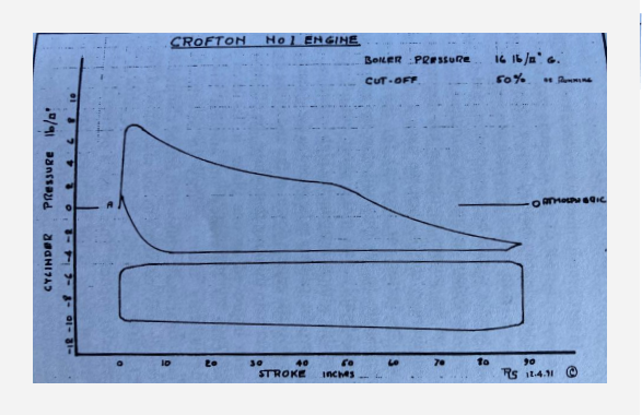
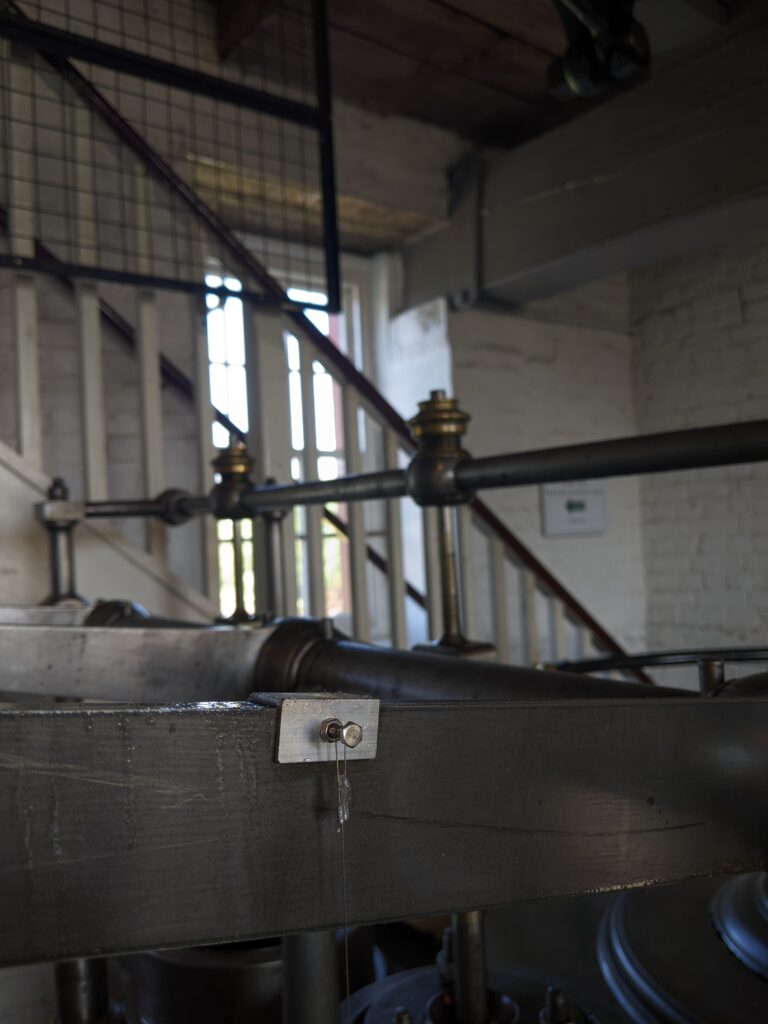
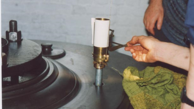
Over the years there have been many designs for instruments to produce Indicator Diagrams. At Crofton we have on display a 19th century Richards Indicator, which was used at Crofton in the 1970s, where it was mounted in place of the lubricator on our No.2 engine. The pressure is measured directly from above the piston and the displacement of the piston, and hence volume, by a string attached to the beam. A paper roll unwinds by clockwork therefore plotting the graph.
Today we are also able to accurately examine the timing of the opening and closure of the valves which we think has not been done before. Overall we believe we are now producing the most accurate measurements ever, for such an historic machine.
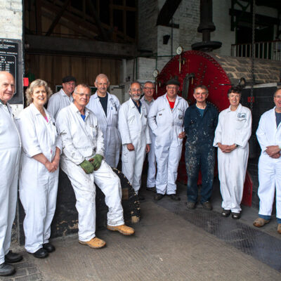
Over the last four years we have been very fortunate to work with undergraduates from the University of Bath and graduates from the Atomic Weapons Establishment (AWE). Bath University students produced an initial Indicator Diagram and went on to calculate the forces on our beams. They also investigated future options if we are no longer able to purchase suitable coal. AWE graduates initiated our Mechatronics programme, exploring options and recommending the Dewesoft system. They have subsequently recommended suitable sensors for beam displacement, valve timings and pressures. They are currently exploring the best way to accurately measure the amount of water pumped.
So far, we have installed thirteen different sensors. Outputs are fed into the Dewesoft Data Acquisition System (DAQ). This produces real time displays for the benefit of visitors and post steaming analysis. Up to 1 million readings are recorded after a typical steaming day. We have identified a number of additional items to measure in the future such as the measurement of the water pumped and the temperature of flue gases.
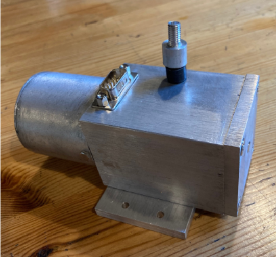

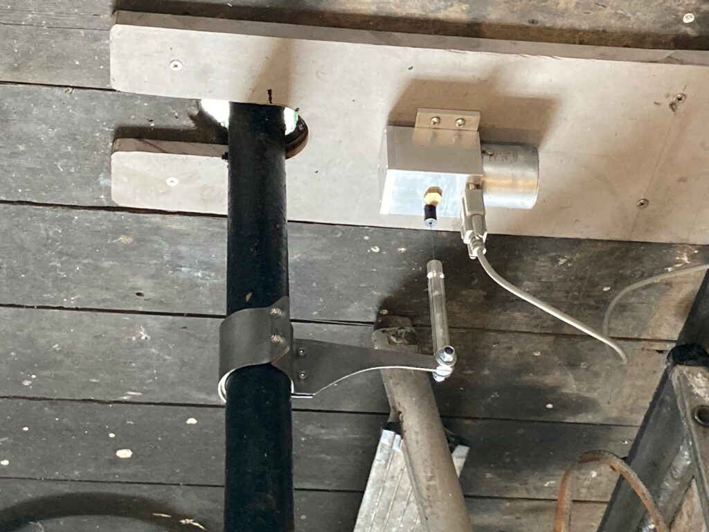
Figure 9 shows a typical Indicator Diagram produced after the engine has warmed up and is running smoothly. It shows both above and below piston pressures and shows that for the major part of the cycle pressures are below atmospheric. The approximate position of the valve timings is also shown
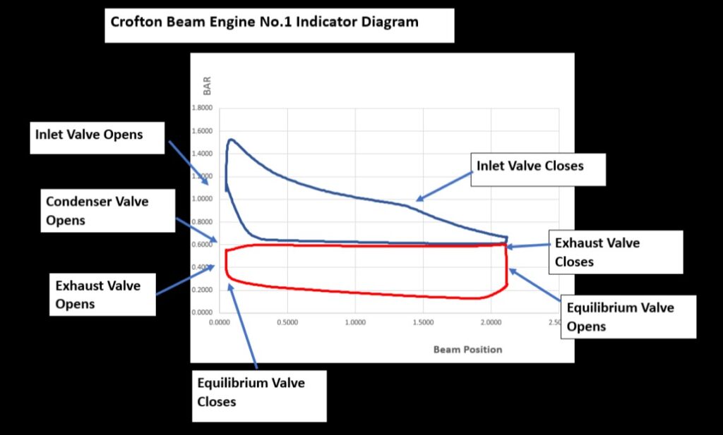
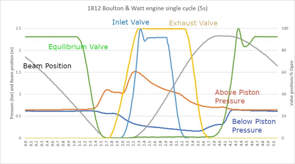
Figure 10 shows the plot of a single cycle of the engine against time. The precise timing of the opening and closing of the valves can be observed. Variations in the pressures over the cycle can be seen, with fluctuations, most likely resulting from leaking valves or the piston.
Earlier this year we experienced a problem with our No.2 engine in that normal operation could not be sustained without driver intervention. Subsequent analysis of the data showed a progressive loss of vacuum. Subsequent examination of the condenser injection valve revealed that it had significantly corroded and displaced, rendering it inoperable and requiring replacement.
We believe our Mechatronics system provides Crofton with a significant tool to assist in enabling our historic machines to continue in operation. We do not think such accurate and detailed information has been obtained from such ancient engines before. By analysing unusual occurrences and comparing results over time we are in a unique position to identify any problems, ensuring early intervention if required. Analysis of the data can also significantly increase our knowledge of how these amazing machines work.

What is Where?
| Engine No. 1 Boulton and Watt 1809 | 2 Pressure sensors (above and below piston pressures) 4 Displacement sensors (valve positions) 1 Displacement sensors (beam position) |
| Engine No. 2 Harvey of Hayle & Co. modified 1903 | 2 Pressure sensors (above and below piston pressures) 1 Displacement sensor (beam position) |
| Lancashire Boiler, bought to Crofton in 1987 | 1 Temperature sensors (top) 1 Pressure sensor (steam pressure) |


